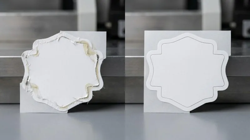
Custom label shapes tearing mid-production isn’t a supplier mystery — it’s a systems failure with identifiable variables. This guide gives you the exact diagnostic framework professional label manufacturers use to eliminate die-cut failures before they shut down your line.
Custom label shapes tear on the production line due to three compounding failure points: grain direction misalignment between the substrate and die orientation, die geometry tolerance drift exceeding ±0.1mm, and adhesive cold-flow migration that undermines cut edge integrity on tight-radius and complex shape geometries.
Each of these variables operates independently — and they compound. Here is how to diagnose which one is killing your run, and the pre-production protocol that stops all three before your first unit rolls off the line.
It Is Not Your Die — It Is Your Grain Direction
Most production managers go straight to the die when custom label shapes start tearing. That is the wrong move.
Grain direction is the most consistently skipped variable in custom die-cut label production — and it causes the most destructive, hardest-to-diagnose tears. Paper and film substrates have a machine direction (MD) and a cross direction (CD).
In paper-based stocks — glassine liners, kraft facestocks, coated papers — fiber alignment runs parallel to the machine direction. When your die cuts against the grain on a tight-radius custom shape, the facestock resists clean separation.
Instead of a precise cut edge, you get micro-tears, lifted fibers, and edge curling that compounds on curved application surfaces and automated dispensers.
“On shapes with an internal corner radius tighter than 3mm, cutting cross-grain increases edge-tear failure rates 3 to 4 times compared to properly aligned runs — across BOPP, kraft, and coated paper stocks.”
Film substrates like BOPP and PET are more forgiving — their molecular structure does not carry the same directional fiber bias. But they introduce a different problem: adhesive cold-flow under tight die geometry, where the adhesive migrates into the cut channel and causes matrix stripping failures during waste removal.
Same symptom on the production floor. Entirely different root cause. That distinction is critical to your diagnosis.
Substrate Sensitivity and Tear Risk Matrix
| Substrate Type | Min. Corner Radius | Grain Sensitivity | Cross-Grain Tear Risk |
|---|---|---|---|
| Coated Paper | 2.5mm | High | Severe |
| Kraft Facestock | 3.0mm | High | Severe |
| BOPP Film | 1.5mm | Low–Medium | Moderate |
| Polyester (PET) | 1.0mm | Low | Low |
| Clear Vinyl | 1.5mm | Low | Low–Moderate |
TL;DR: If your priority is sharp aesthetics, carefully align paper grain; if you face ultra-complex shapes, invest in PET substrates to eliminate tear risk.
Where ±0.1mm Decides Whether Your Production Run Lives or Dies
Assume your grain direction is correctly aligned. The next variable — die geometry tolerance — is where precision either holds or quietly drifts into failure at the worst possible moment.
In rotary die-cutting for custom label shapes, the acceptable variance between blade edge and liner surface is ±0.1mm. Exceed that on the shallow side and you get incomplete cuts — labels that look intact but tear the moment they reach the applicator head.
Exceed it on the deep side and you are scoring the liner, compromising web integrity, and setting up a catastrophic matrix break mid-run at full line speed. What makes this particularly damaging is that the tolerance is not static. It drifts with every impression.
Rotary die tooling undergoes measurable wear after approximately 500,000 to 800,000 linear impressions, depending on substrate hardness and adhesive aggressiveness. A die cutting cleanly on your first order will not perform identically on your sixth if impression counts have not been tracked or tooling reconditioned.
This is the most consistent — and most avoidable — source of progressive tear failure in repeat custom label production runs.
The shape characteristics that concentrate die geometry stress most aggressively:
- Internal corners with radii below 2mm
- Bridges or connecting elements narrower than 3mm
- Aspect ratios exceeding 8:1 length to width
- Multi-point or petal designs with tip angles below 30°
The ask your supplier is not expecting: request die impression logs on every repeat order. If they cannot produce that data, your production quality is running on assumption, not process control. A technically competent facility tracks this as standard practice. The ones that cannot are telling you something important before your run hits their floor.
The Adhesive Compatibility Trap That Quietly Destroys Complex Custom Shape Runs
Perfect grain alignment. Freshly reconditioned die running at ±0.1mm. And your custom label shapes are still tearing during matrix stripping. Now you are looking at adhesive-substrate compatibility — the most expensive and least-discussed failure vector in die-cut label production.
The trap is structural: adhesive selection is almost always optimized for the application surface, not the die-cutting process. Aggressive high-tack acrylic adhesives — commonly specified for corrugated or rough-surface applications — have a measurable cold-flow tendency at the cut edge.
Under rotary die pressure, the adhesive layer migrates laterally by 0.05mm to 0.12mm into the cut channel. On standard rectangular labels, that is inconsequential. On complex custom shapes with tight internal corners or acute tip angles, that same migration undermines cut edge integrity at precisely the highest structural stress points.
A craft beverage client running a custom shield-shaped label on 60# coated paper with high-tack permanent adhesive saw clean output for the first 2,000 units. By unit 2,500, consistent tearing appeared at both 25° internal corners during matrix removal.
Cross-section analysis under magnification confirmed adhesive migration of 0.09mm into the cut channel. Switching to a medium-tack adhesive with a higher viscosity index reduced migration to under 0.03mm. Tear rate dropped to zero. The die, substrate, and grain direction had all been correct from the start.
Adhesive Cold-Flow Risk Assessment
| Adhesive Type | Cold-Flow Risk | Min. Corner Radius | Suitable for Complex Shapes |
|---|---|---|---|
| High-Tack Acrylic (Permanent) | High | 3.5mm+ | No |
| Medium-Tack Acrylic | Low–Medium | 2.0mm | Yes |
| Rubber-Based Permanent | Medium | 3.0mm | Conditional |
| Low-Tack Removable | Very Low | 1.5mm | Yes |
| Emulsion Acrylic | Low | 2.0mm | Yes |
TL;DR: If your priority is maximum surface adhesion, avoid tight corners; if you face structural edge tearing, specify a low-flow emulsion acrylic.
The mitigation is direct: request an adhesive cold-flow assessment on your actual die geometry for any custom shape with internal corner radii below 3mm.
This is standard capability at any technically mature label manufacturing facility. Resistance or confusion in response to that request tells you everything you need to know about process maturity — before the production run, not after.
Ready to End Die-Cut Downtime on Your Production Line?
Don’t let tight geometries and substrate mismatches stall your applicators. We engineer machine-ready custom die-cut labels with a rigorous Free Pre-Press Audit to guarantee zero edge-tearing.
The Pre-Production Protocol That Eliminates All Three Custom Label Tearing Vectors
Reactive troubleshooting after a failed run costs more in every dimension than structured validation before it. The protocol below adds roughly 48 hours to your pre-production timeline. It eliminates the three-to-five day fire-drill that follows a failed first run almost entirely.
Step 1 — Shape Complexity Audit Before Die Fabrication:
Evaluate your approved artwork against four quantifiable criteria — minimum internal corner radius, minimum bridge width, maximum aspect ratio, and number of directional perimeter changes.
Any shape hitting critical thresholds requires explicit die compensation engineering: adjusted bevel angles on high-stress corners, strategic nick placement to manage matrix strip tension, and mandatory pull-test validation on the first 50 pieces before full-run approval is granted. Document this audit in writing and get supplier sign-off on the job ticket.
Step 2 — Substrate-Adhesive Compatibility Test on Your Actual Die Geometry:
Spec sheets are tested on rectangular samples under controlled laboratory conditions. Your complex custom shape is not a rectangle. Request a 50-piece sample cut on your exact die with the specified adhesive and facestock combination, tested at both ambient temperature (~20°C) and your facility’s lower operating range.
Adhesive performance on complex custom label shapes changes measurably below 15°C — cold-flow migration decreases, but brittle edge fracture risk on narrow bridges increases. A supplier testing only at room temperature is giving you half the data.
Step 3 — Impression-Count Documentation on Repeat Tooling:
Establish a reconditioning trigger in your supplier agreement — not as an informal assumption. For complex custom shapes, a conservative threshold of 600,000 impressions is a defensible standard. Get it in writing and tie it to your quality agreement before the order is placed.
The ROI of Pre-Production Validation
| Cost Category | Pre-Production Validation | Failed First Run (50K Units) |
|---|---|---|
| Direct Cost | $150 – $400 | $4,000 – $12,000 |
| Timeline Impact | +48 hours | +3 to 5 business days |
| Downstream Risk | Negligible | Retail deadline penalties |
TL;DR: If your priority is supply chain velocity, absorb the +48 hours pre-flight; if you face strict margin controls, the $400 validation is mandatory insurance.
How to Qualify a Die-Cut Label Supplier Before Your Custom Shapes Hit Their Floor
Everything covered above converges on one operational question: does your current label supplier have the technical infrastructure to manage these variables proactively — or reactively, after your custom label shapes have already failed?
The US market consolidates around two supplier archetypes. The transactional converter is competitive on price and reliable on standard shapes. The technically capable manufacturing partner runs in-house engineering review, documented tooling management, and a pre-production process that catches complexity risks before they become production failures.
The price gap between these two on a complex custom shape order is typically 8–15%. The cost gap when the transactional supplier fails your run is an order of magnitude larger.
Supplier Technical Audit Checklist
| Qualification Criterion | What to Ask | Acceptable Response |
|---|---|---|
| Die Tooling Management | “Can you provide impression count logs for repeat tooling?” | Yes, with documented records |
| Grain Direction Protocol | “How do you confirm grain alignment for complex shapes?” | Written pre-press checklist |
| Adhesive Compatibility Testing | “Do you test adhesive performance on the actual die geometry?” | Yes, with shape-specific samples |
| Complexity Audit Process | “What triggers a design review before die fabrication?” | Defined threshold criteria |
| Pre-Production Validation | “What does your first-article inspection process include?” | Pull-test data and documented sign-off |
TL;DR: If your priority is long-term stability, demand impression logs; if you face an immediate critical launch, enforce the first-article pull-test validation.
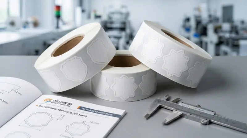
One specification detail that almost never appears in standard procurement conversations: specify 3-inch core winding on complex custom label shape rolls, rather than the standard 1-inch core.
Roll tension stress on narrow bridges and acute-angle tips during cross-country freight — particularly across temperature differential zones in summer and winter months — causes micro-tears that are consistently misattributed to production quality rather than shipping handling.
It costs nothing to add to your purchase order. It prevents an entire failure category.
Custom label shapes tearing on your production line is a systems problem with specific, addressable variables distributed across material science, tooling engineering, adhesive chemistry, and supplier process maturity.
The buyers who stop losing production runs to die-cut failures are not the ones who found a better die or a cheaper substrate. They are the ones who mapped the full variable set, built a pre-production protocol around it, and chose suppliers equipped to execute against documented technical standards.
That is the standard your production line deserves — and now you have the framework to demand it.